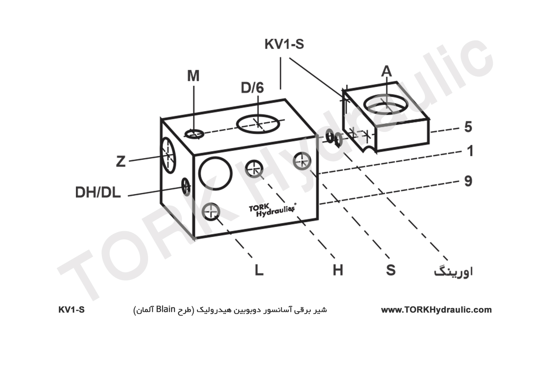
Solenoid valve / Double coils
Up movement in KV1-S lift valve
One up speed, 0.16 m/s (32 fpm) max. Up start has built-in damping. Up stop has no damping (pump stops).
For the correct installation and safety of the elevator, the correct installation of the solenoid valve, which is one of its components, is very important and negligence in this regard can lead to irreparable accidents and loss of life and property. And it should be in accordance with the principles and content of the guide. The following are the up and down movement settings of the elevator and the control elements and adjustment parameters of the TORK hydraulic two-coil valve.
One up speed, 0.16 m/s (32 fpm) max. Up start has built-in damping. Up stop has no damping (pump stops).
One down speed, 0.16 m/s (32 fpm) max.
Down start has adjustable damping.
Down speed is adjustable.
Down stop has built-in damping.
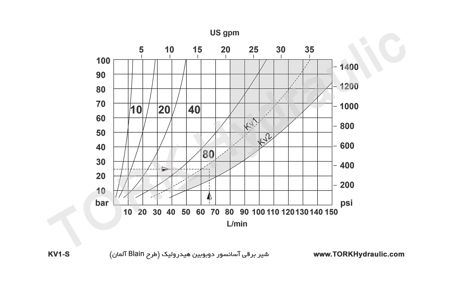
Flow Range:
5-80 l/min (1.3-21 US gpm) - see flow pressure charts.
Pressure Range:
8-100 bar (116-1450 psi)
Burst Pressure:
500 bar (7251 psi)
Coils AC:
24 V/1.8 A, 42 V/1.0 A, 110 V/0.5 A, 230 V/0.18 A, 50/60 Hz
Insulation Class: AC and DC: IP 68
Coils DC:
12 V/2.1 A, 24 V/1.1 A, 42 V/0.6 A, 80 V/0.3 A, 125 V/0.25 A, 196 V/0.14 A.
Oil Viscosity:
25-60 cSt. at 40°C (104°F) Max. Oil Temperature: 70°C (158°F)
Operation oil temperature range:
10°C-60°C (50°F-140°F), for oil VGA46: 250cSt.-20 cSt.
Optimal oil temperature range:
25°C-55°C (77°F-131°F), for oil VGA46: 100cSt.-24 cSt.
Ambient temperature range:
0°C-70°C (32°F-158°F)
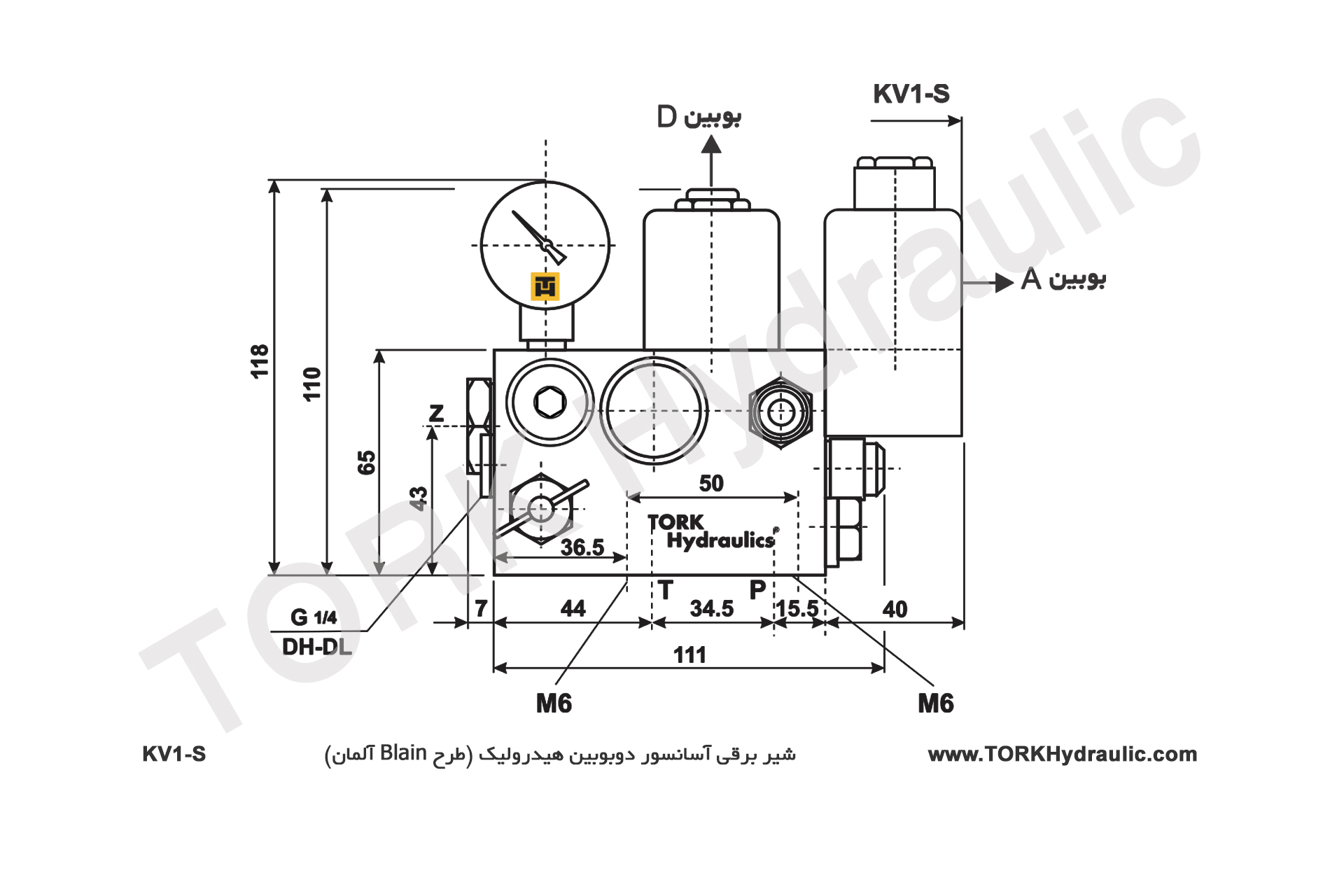
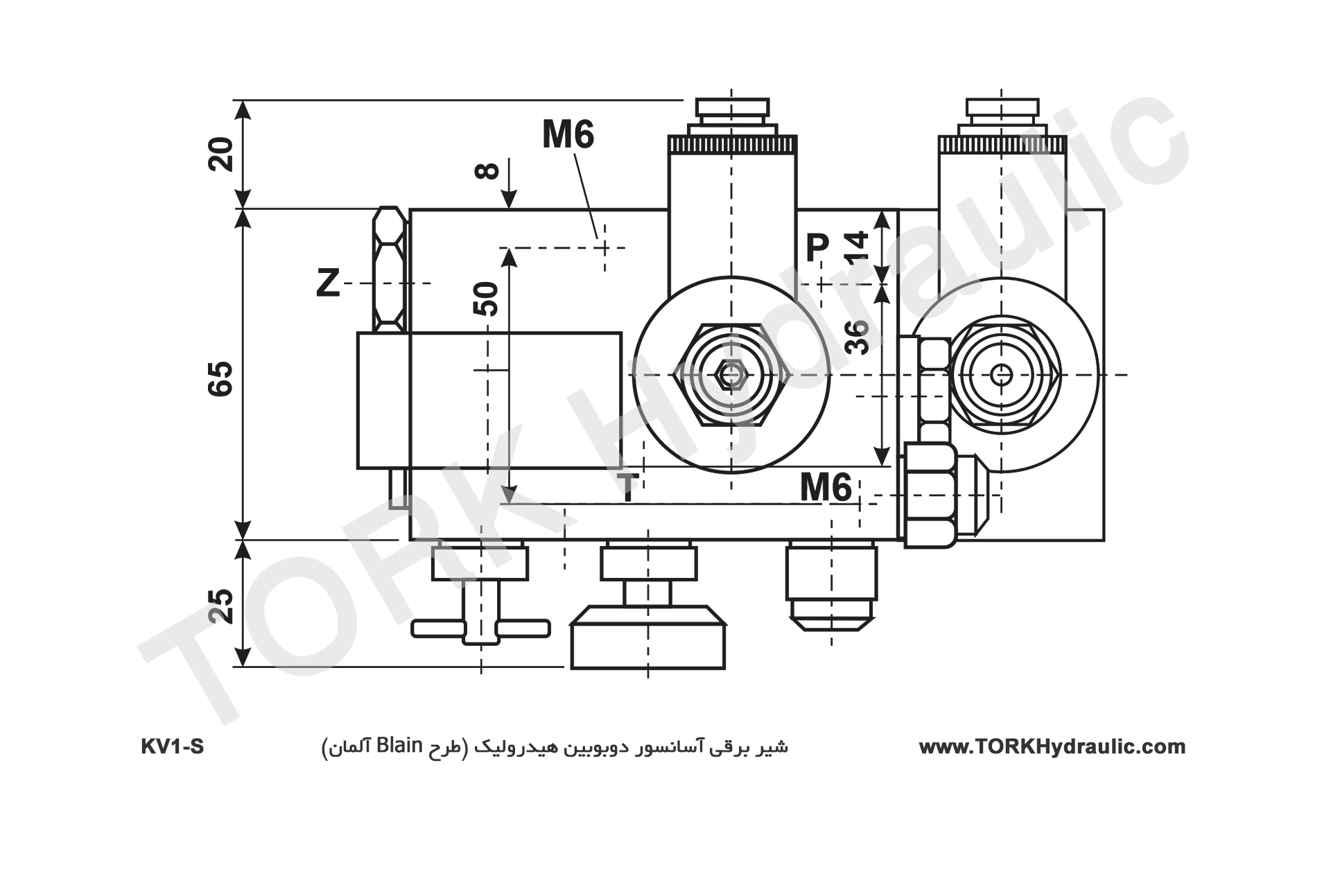
Ports:
P Pump, Z Cylinder and T Tank all G½
Warning
Only qualified personnel should adjust or service valves. Unauthorised manipulation may result in injury, loss of life or damage to equipment. Prior to servicing internal parts, ensure that the electrical power is switched off, cylinder line is closed and residual pressure in the valve is reduced to zero.

Valves are already adjusted and tested. Check electrical operation before changing valve settings. Test that the correct coil is energized, by removing the nut and raising the coil slighty to feel pull.
KV1-S 1. Up Bypass:When the pump is started, the unloaded car should remain stationary at the floor for a period of about 1 second before starting upwards. The length of this delay is according to the setting of adjustment 1. 'In' (clockwise) shortens the delay, 'out' (c-clockwise) lengthens the delay.
Screw No. 5 is for adjusting the soft stop at the topAt stop station, coil A is switched off. By using the electric timer in the electrical panel of the pump, it works for about 1 second more so that the cabin has a smooth stop. The softness value of the stop is set to 5. In the clockwise direction the stop becomes softer and in the anti-clockwise direction the stop becomes sudden and faster.
Preset: While coil A is disconnected and the pump is running, rotate 5 inwards until the cab starts to move, then rotate until the anti-clock cab stops.
Another way to set the stop above:At relatively high speeds, despite the timer in the power circuit, the cabin may travel slightly more than the station level to stop at the station. In these cases, the lowering coil D is actuated so that the cab slowly lowers and switches off at the level of the coil D floor.
S Relief Valve:'In' (clockwise) produces a higher, 'out' (c-clockwise) a lower maximum pressure setting. After turning 'out', open manual lowering H for an instant. Important: When testing relief valve, close ball valve gradually.
WarningValves are already tested and adjusted. Check electrical operation before changing valves settings. Test that the correct coil is energized by removing nut and raising the coil slightly to feel pull.
When coil D is energized, the car will accelerate downwards according to the setting of adjustment 6. 'In' (clockwise) provides a softer down acceleration, 'out' (c-clockwise) a quicker acceleration. Pre-adjustment: Turn adj. 6 all the way in and then energize coil D. Turn 6 slowly back out until the car accelerates downwards.
9. Down Speed:With coil D energized as above, the down speed of the car is according to the setting of adjustment 9. 'In' (clockwise) provides a slower down speed, 'out' (c-clockwise) a faster down speed.
Down Stop:At fl oor level, coil D is de-energized causing the car to stop. No adjustment necessary.
H Manual Lowering:'out' (c-clockwise) allows the car to be lowered by hand. Closes automatically on release.
Important: Use a 3/4 hose for better valve performance and to prevent pressure drop. Pump flow above 80 liters is not recommended.
Caution: After completing the KV1-S valve settings, be sure to close the manometer valve to prevent the manometer from malfunctioning.